This page, 'Flow in the U9 model', should be part of a frames system at www.tfd.chalmers.se/~lada/projects/proind.html
Numerical Investigations of the Flow in the U9 Model
| Researcher: |
Olivier Petit olivierp@chalmers.se |
||||||
| Supervisor: |
Håkan Nilsson hani@chalmers.se |
||||||
| Examiner: |
Lars Davidson lada@chalmers.se |
||||||
| Cooperation: |
C3SE, Chalmers GE Energy (Sweden) AB GE Intra, Energy, Canada |
||||||
| Sponsors: |
The Swedish National Energy Admininstration GE Energy (Sweden) AB The Swedish Electrical Utilities R&D Company |
||||||
| Publications: | [-] | ||||||
| Start of project: | October 2007 | ||||||
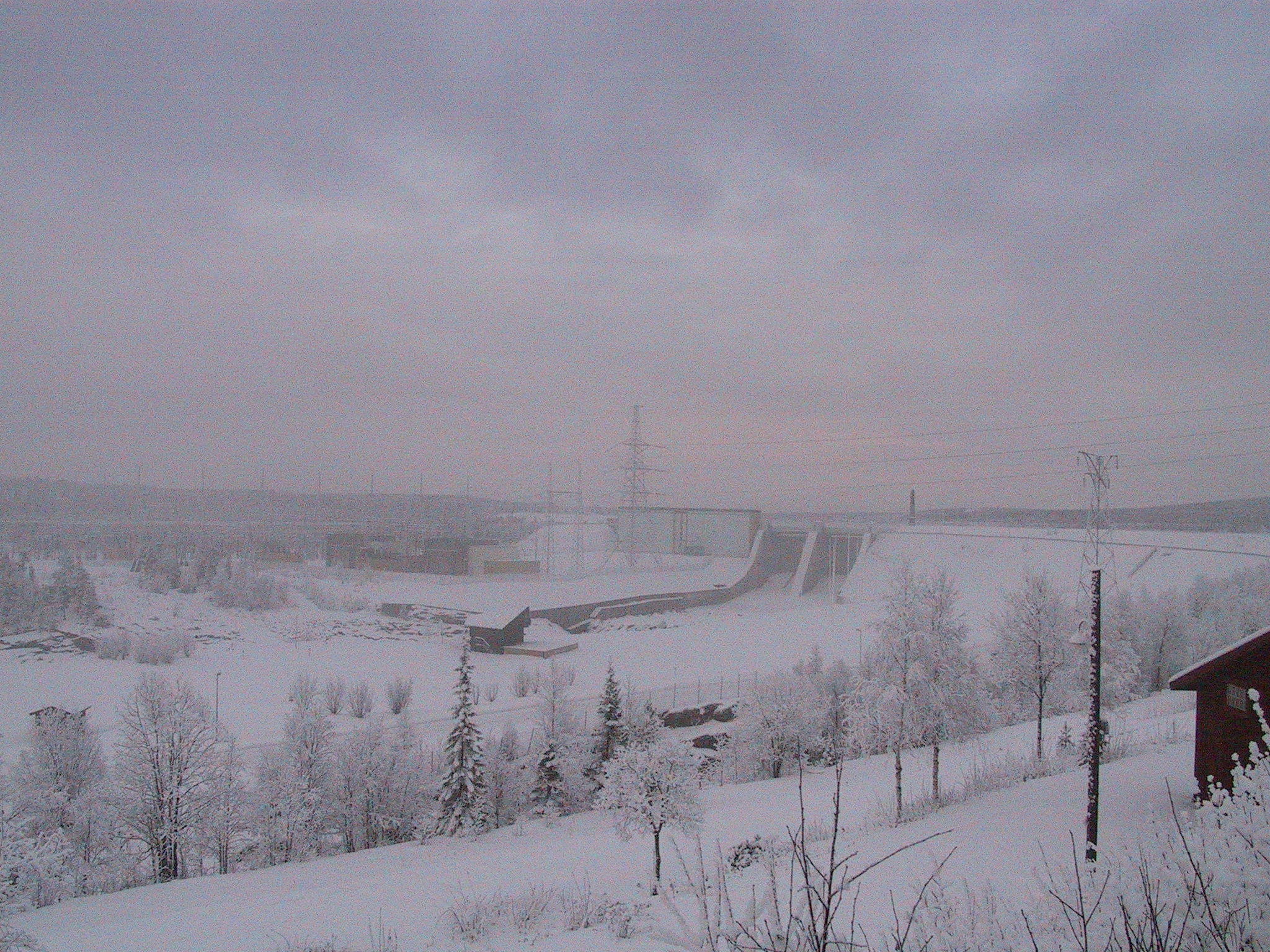
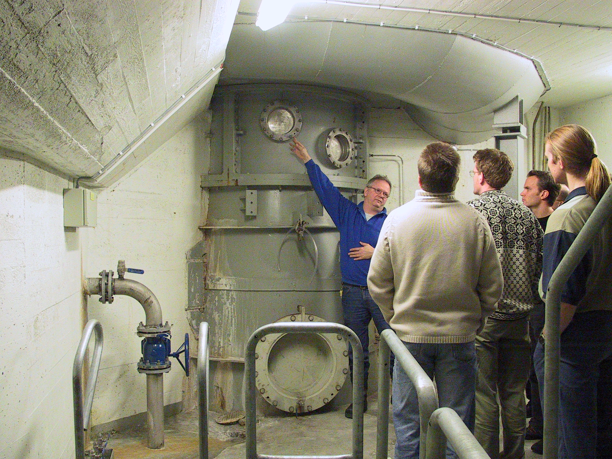
BACKGROUND The U9 Kaplan turbine is a unique combination of model- and full scale research units. The full scale turbine is located in Porjus, in the most northern parts of Sweden (see figs. 1-3 below), and the model scale turbine is located at Vattenfall Research and Development in �lvkarleby, in the center of Sweden. In the initial phase of the project the focus is on the flow in the casing and distributor. Later on in the project also the runner and the draft tube, and the coupling between the different parts of the system will be studied. One of the main aims of the project is to study the influence of different choices of boundary conditions on the computed flow. The OpenFOAM CFD code is used for the simulations at Chalmers. CFX simulations are made by GE for comparison. With similar settings for the simulations it is possible to compare different aspects of the simulations, such as accuracy, efficiency and general features of the two codes. Detailed measurements of the flow in both full scale and model scale will be made in other PhD projects, and those will be used to validate the numerical results.
PUBLICATIONS
THE FLOW IN THE U9 KAPLAN TURBINE - PRELIMINARY AND PLANNED SIMULATIONS USING CFX AND OPENFOAM Olivier Petit, H�kan Nilsson, Thi Vu, Ovidiu Manole, Svante Leonsson Chalmers / Chalmers / Andritz VA Tech Hydro Ltd., Canada / Andritz VA Tech Hydro Ltd., Canada / Andritz Hydro Inepar Sweden AB 24th IAHR Symposium on Hydraulic Machinery and Systems, Foz do Iguassu, Brazil, October 27-31, 2008 Abstract The present work compares the CFX and OpenFOAM CFD codes with respect to the prediction of the flow in the U9 Kaplan turbine spiral casing, distributor and draft tube. The simulations use similar settings and the same computational grids � unstructured wall-function grids with 10.3M cells in the spiral casing and distributor, and 1.04M cells in the draft tube. The results show that the two codes give similar results in the spiral casing and distributor, and almost identical results in the draft tube. Previous studies [1] have shown the same behaviour in the Turbine-99 draft tube, for a block-structured wall-function grid. There are however no previous studies where the flow in a spiral casing and distributor have been studied and compared using the same settings and computational grid in CFX and OpenFOAM. The next phase of the project consists of comparisons with the results from an on-going experimental investigation. KEY WORDS: CFD, Water Turbine, Draft Tube, Spiral Casing, Distributor, CFX, OpenFOAM
The ERCOFTAC centrifugal pump OpenFOAM case-study Olivier Petit, Maryse Page, Martin Beaudoin and Hakan Nilsson Chalmers / IREQ, Hydro Quebec / IREQ, Hydro Quebec / Chalmers 3rd IAHR International Meeting of the Workgroup on Cavitation and Dynamic Problems in Hydraulic Machinery and Systems, October 14-16, 2009, Brno, Czech Republic Abstract This work investigates the rotor-stator interaction features of OpenFOAM-1.5-dev, such as frozen rotor and sliding grid. The case studied is the ERCOFTAC Test Case U3: Centrifugal Pump with a Vaned Diffuser, a testcase from the ERCOFTAC Turbomachinery Special Interest Group. The case was presented by Combes at the ERCOFTAC Seminar and Workshop on Turbomachinery Flow Prediction VII, in Aussois, 1999. It is a valid test case for evaluation of rotor-stator interaction features, as detailed experimental data is available. The investigation shows that OpenFOAM gives results that are comparable to the experimental data, in particular for the sliding grid case. The results are less accurate in the frozen rotor simulation due to the improper treatment of the impeller wakes that is part of the frozen rotor formulation. The ERCOFTAC centrifugal pump OpenFOAM case-study was developed as a contribution to the OpenFOAM Turbomachinery Working Group, and was presented and discussed at the Fourth OpenFOAM Workshop in Montreal, 2009. The complete set-up of the case-study is available from the OpenFOAM-extend project at SourceForge, and instructions and comments are available from the OpenFOAM Wiki.
KEYWORDS
Numerical Investigations of Incompressible Turbomachinery Applications using OpenFOAM Olivier Petit, Thesis for the degree of licentiate of engineering in thermo and fluid dynamics, 2010:02, Div. of Applied Mechanics, Chalmers University of Technology, Gothenburg. Abstract Swirling flow and unsteady phenomena are common in technical applications, such as turbines, pumps and compressors. The objective of this work is to get a good understanding of the turbulent flow features inside such applications, and to validate the computational techniques used for such applications. Because of the complexity of the turbulent flow, approximations are made when solving the flow equations in the computational domain. Depending on the level of the approximations, the level of accuracy and detail in the predicted flow will vary. To validate the assumptions used in the simulations and to get a good prediction of the flow, the computational technique as well as the CFD code must thus be validated against detailed measurements. The present work aims at getting a good understanding of the turbulent flow in the U9 Kaplan turbine model, using the OpenFOAM CFD code. Detailed measurements are used to validate the computed turbulent flow features. Two methods are used in this present work to predict the interaction between rotating and stationary parts of the machines. The steady-state method coupled with the frozen rotor approach solves the time-averaged Reynolds Averaged Navier Stokes equations, while the unsteady method with the sliding grid approach solves the same equations taking the time dimension into account. To validate the two different computational techniques, comparisons between computational results and detailed measurements for two different case studies are performed: the ERCOFTAC centrifugal pump, and a swirl generator test rig. Good agreement is found between numerical and experimental results. If you download a document or have any comments concerning the work or the web-page, please send me an e-mail or let me know by filling up this form:
- click BACK TO TOP |
||||||
|
This page, "Flow in the U9 model", should be part of a frames system at www.tfd.chalmers.se/~lada/projects/proind.html |